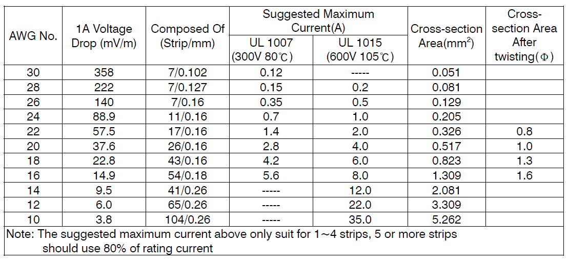
To install a power supply into the system, you would need wires for the connection both to the loads and to the energy source. There are a couple of points that should be taken into consideration when choosing wires, one is current rating, it may cause high heat on the wires or burnt out in the worst case, if the rating is not enough. The other is voltage drop, there would be voltage reduction at load side as current moves through the wires owing to the internal resistance. If too much voltage drop in line, there could be no sufficient voltage to drive the loads. You can find the right wires for use by referring to the table below on the basis of your system design.
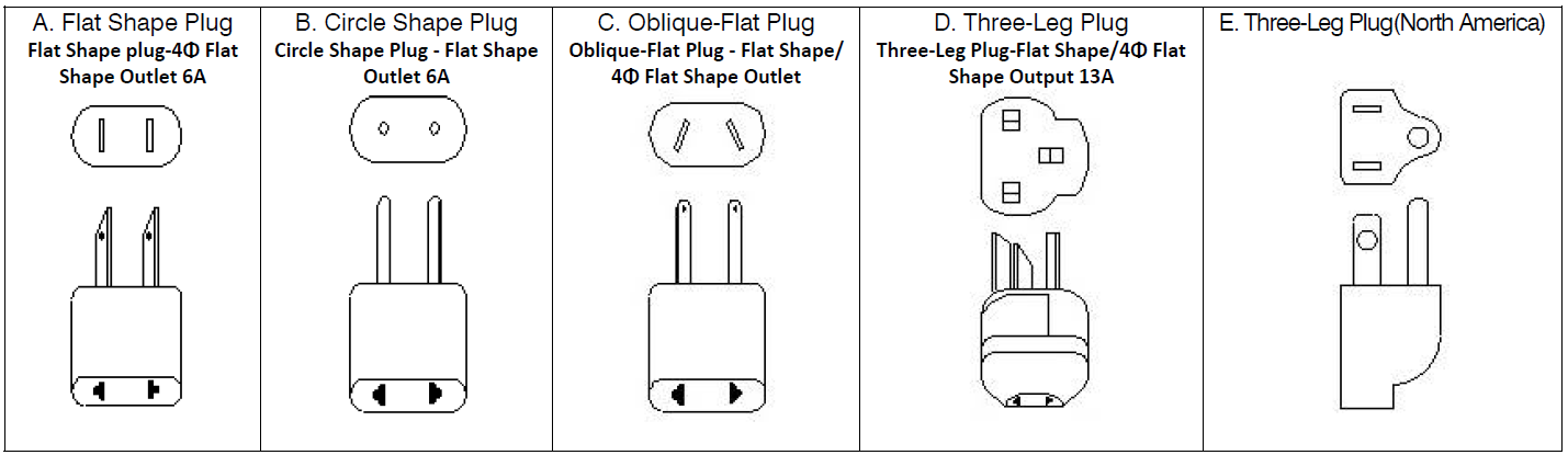
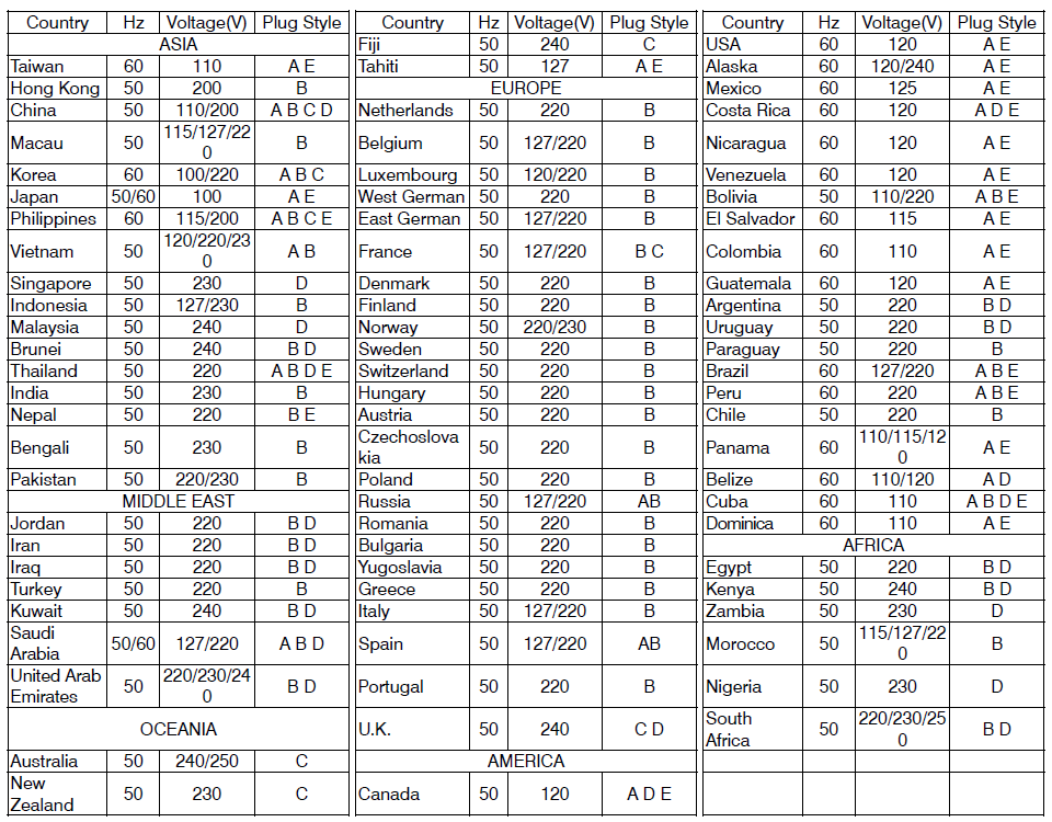
An adaptor may need connection of a power cord to receive energy needed from the utility. You can refer to the specification of the adaptor for the connector (AC inlet) at the adaptor end of the power cord; Different countries/regions vary in type of AC socket and voltage, please look at the table below for the information of the AC plug you need.
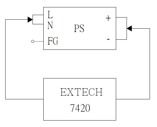
There are two different applications when PSU are connected in series. One is to generate plus minus voltage, another is to increase total output voltage. Connection methods are as follows:
(1) Connection for plus and minus voltage are shown as follow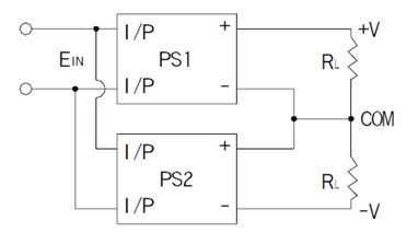
(2) To increase the total output voltage (Output current remain the same). Diode connect in parallel at output
side of the driver is necessary to prevent damage during start up. The voltage rating of diode shall greater
than V1 + V2( shown as figure below), in addition, peak forward surge current rating shall greater than
rated current.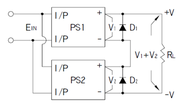
* Because part of the signal ground is shorted with output ground, strongly suggest to use isolated signals to
achieve control scheme, in order to prevent damage to the product.
When power supplies are connected in parallel, mostly, is intent to increase the output current. Due to the design of active current sharing, they are mostly without reverse current protection, therefore, they are not the best solution when talking about redundancy. For redundant purpose, please choose the PSU with redundant function or implement external redundant modules. Be sure that the difference in output voltage and wiring impedance, should be as small as possible.
1. Use PSP models as example, connect P(LP/CS) terminals together (Please refer to the parallel function of
specification). Input and output should be connected in parallel before connecting to the AC source and
loads. Shown as in picture below (some S.P.S. require a minimum load after paralleling).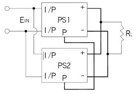
2. Output voltage difference between S.P.S. units should be as small as possible, normally < 0.2V.
3. The power supplies should be paralleled with short and large diameter wiring together first, and then
connected to the load.
4. After paralleling, the maximum usage of total power should be around 90% of the rated total power.
5. When power supplies are paralleled, if the load is lower than 10% of rated load of individual S.P.S. The LED
indicator or signals (Power Good、Pok、Alarm Signal) may malfunction.
6. To ensure that the load current is effectively shared in parallel operation, in general, it is recommended not to
use more than 4-6 power supplies at one time.
7. In some models, the +S, -S terminals should be used to reduce unstable pulsation of output voltage.
MTBF (Mean Time Between Failure) and Life Cycle are both indicators of reliability. MTBF can be calculated by two different methodologies, which are “part count” and “stress analysis”. The regulations, MIL-HDBK-217F Notice 2 and TELCORDIA SR/TR-332(Bellcore) are commonly used to calculate MTBF. MIL-HDBK-217F is a United States military standard, and TELCORDIA SR/TR-332(Bellcore) is a commercial regulation. UWIN utilize MIL-HDBK-217F(Stress Analysis) as the core of MTBF. The exact meaning of MTBF is, after continuously using the power supply for a certain amount of time, the average time that the probability of proper operation is down to 36.8%(e-1=0.368). Currently UWIN is adopting MIL-HDBK-217F, forecasting the expected reliability through Stress Analysis (excluding fans); this MTBF means the probability of the product can continue the normal work after working continuously up to the calculated MTBF time is 36.8% (e-1=0.368). If the power supply is continuously used at double the MTBF time, the probability of proper operation becomes 13.5%(e-2=0.135). Life Cycle is found by using the temperature rise of electrolytic capacitors under maximum operating temperature to estimate the approximate life of the power supply. For example, RSP-750-12 MTBF=109.1K hours(25°C); electrolytic capacitor C110 Life Cycle=213K hours (Ta=50℃)
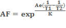
DMTBF(Demonstration Mean Time Between Failure) is a way of evaluate MTBF。Please refer to the following equation for MTBF calculation.

Where
MTBF:Mean Time Between Failure
X2:Can be found in chi-square distribution
N:Number of sampling
AF:Acceleration factor, which can be derived from acceleration factor equation.
Ae=0.6
K(Boltzmann Constant)=(eV/k)
T1:Rated temperature of specification. Note: Kelvin will be the unit use for calculation
T2:The temperature that is used in the meaning of acceleration, and the chosen temperature could not result in physical change in materials. Note: Kelvin will be the unit use for calculation.
When current drawn exceeds the rating of the PSU, the protection circuit will be triggered to protect the unit against overload/over current.
Protections of overload/over current can be divided into several forms:
(1)FOLDBACK CURRENT LIMITING
Output current decreases about 20% of rated current, shown as curve (a) in the figure below.
(2)CONSTANT CURRENT LIMITING
Output current remains at a constant level and within the specified range while the output voltage drops to a lower level, shown as curve (b) in the figure below.
(3)OVER POWER LIMITING
Output power remains constant. As output load increases, output voltage decreases in proportion, shown as curve (c) in the figure below.
(4)HICCUP CURRENT LIMITING
Output voltage and current keep pulsing ON and OFF repeatedly when protection is activated. The unit automatically recovers when faulty condition is removed.
(5)SHUT OFF
Output voltage and current are cut off when output load reaches protection range.
NOTE: Protection mode of some of the products combines with different types of the forms mentioned, such as constant current limiting + shut down.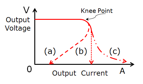
Recover method:
(1)Auto Recovery: PSU recovers automatically after faulty condition is removed.
(2)Re-power on: PSU restarts by manual AC re-power on after faulty condition is removed.
Note:Please do not operate PSU in over current or short-circuit condition for a long period of time to prevent a shorten lifespan or damaging the PSU.
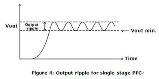
It is the small unwanted residual periodic variation of the direct current (DC) output of a power supply which has been derived from an alternating current (AC) source. The wave form is shown as figure below.
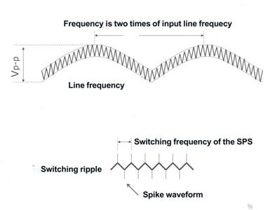
There are two AC contents, also known as Ripple and Noise (R&N), on the DC output. The first one, coming from sine wave rectification, is at a low frequency which is 2 times of the input frequency; the second one is at high frequency which is from the switching frequency. For measuring high frequency noise, configurations of an oscilloscope with a bandwidth of 20MHz, a scope probe with shortest ground wire possible, and add 0.1uF and 47uF capacitors in parallel with test point for filtering out noise interference are requires to be made.
Indicates Hi-Pot Test or Electric Strength Test. The input should be shorted together as well as the output before test. The test will proceed under particular loop, such as I/P-O/P, I/P-FG and O/P-FG with certain high voltage value for 1 minute. (The typical leakage current is 25mA when testing with AC)